PART IIInstallation
CHAPTER 7
Measurement modules and Failover
7.1 Measurement modules (BUS ports)
The BUS ports take the modules that widen what the Controller sees in the water. Each installed module makes the corresponding sensor "wake up" on the Sensors screen — detection is automatic, at equipment start-up:
| Module | What it measures | Units |
|---|---|---|
| pH (A and B) | Water pH — up to two independent modules | pH |
| ORP | Oxidation-reduction potential | mV |
| EC | Conductivity / salinity | µS/cm, mS/cm, ppt, specific gravity, kg/m³ |
| TDS | Total dissolved solids — ideal for RO water | ppm |
| Oxygen (SAT/DO) | Dissolved oxygen saturation | % or mg/L |
| Aquarino KH | Alkalinity, measured by the integrated Aquarino KH (Chapter 24) | dKH, ppm, mEq/L |
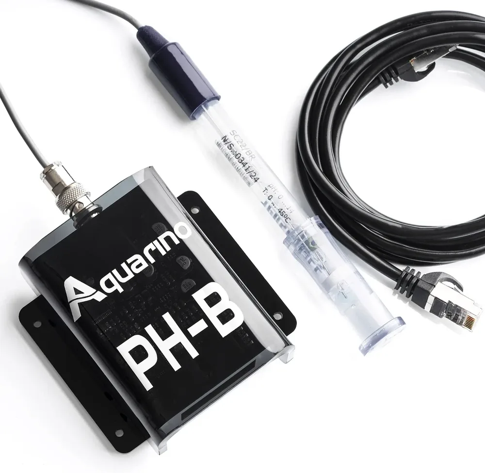
- Unplug your Aquarino.
- Connect the module to any BUS port.
- Power it back on and check the reading on the Sensors screen.
- Calibrate the probe before trusting the readings — Chapter 20 has the step-by-step for each one.
7.2 Failover module
The Failover is the brains behind your aquarium's UPS: it monitors voltage, current and consumption (kWh), detects the power outage and turns off the outlets you marked as non-essential — so the battery lasts longer for what matters.
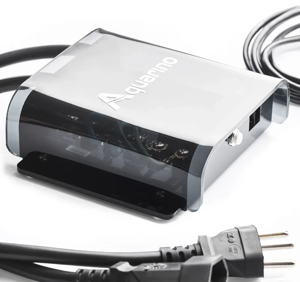
- Unplug your Aquarino.
- Connect the Failover module's network cable to a BUS port on the hub.
- Connect the module's male plug to the mains supply.
- Connect the module's female socket to the UPS.
- Plug the Powerbar and the Aquarino into the UPS.
- Power the Aquarino on and calibrate the voltage in System → Calibration (Chapter 20).
| Characteristic | Value |
|---|---|
| Maximum current | 25 A |
| Voltage | Universal — detects 110 V or 220 V automatically |
| Communication cable | 5 metres maximum |
| Sensors it enables | Volts, Amps and Power (consumption in W and kWh) |
How the system behaves during a power outage — and how to configure each outlet for it — is in Chapter 23.