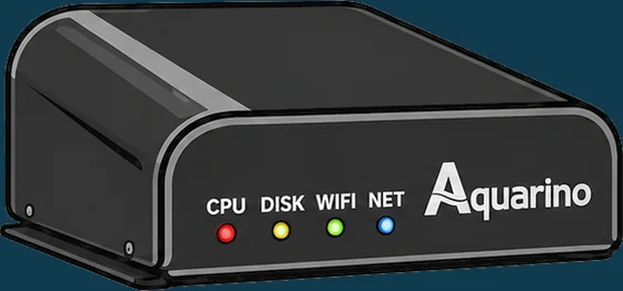
AQUARINO CONTROLLER
Automation and monitoring hub for aquariums, tanks and ponds.
Preface
Like every aquarist, I looked for what was best for my fauna and flora; it took a lot of equipment, products and study.
After buying several devices to monitor, control and help me care for my aquarium, I realised that none of them met my needs perfectly. There was difficult setup, high cost and plenty of limitations.
So I decided to use my knowledge of technology, and my own resources, to offer our hobby a new option. That is the moment Aquarino was born.
I am very proud of what we have built. Many aquarists took an active part, sending suggestions. We only reached this result because you believed in the project.
What we want to keep as the essence of Aquarino is direct contact with aquarists, close support and service, and speed in delivering new features and products.
Join our channels to ask questions, send suggestions and talk about the hobby:
- WhatsApp: https://chat.whatsapp.com/IcFxySY8rgi3Inkenbbs3l
- Facebook: https://www.facebook.com/AquarinoController
- YouTube: https://www.youtube.com/c/aquarino
Aquarino depends on all of us to move forward and become a reference in usability, features and service for aquarists worldwide.
Thank you! We will repay your trust, and take our hobby to a new level.
Laercio M F Junior
Founder and Director of Innovation, Aquarino
How to use this manual
This manual is meant to be read in order the first time, and consulted by topic afterwards. If your Aquarino Controller has just arrived, follow Parts II and III in sequence — in under an hour it will be connected and controlling its first outlets.
Five kinds of highlight appear throughout the text:
The screenshots were taken in the Local Manager — the interface the equipment itself serves on your network — on a phone, which is how most aquarists use the Aquarino day to day. The same screens exist in the Aquarino app.
Getting to know your Aquarino Controller
What the hub does, what is in the box and how it makes decisions.
What the Aquarino Controller is
The Aquarino Controller is an automation and monitoring hub for aquariums, tanks and ponds. It brings together, in a single piece of equipment, the readings from your sensors, the control of the outlets, the dosing pumps, the automatic feeder and the rules that tie it all together — with access over your Wi-Fi network and over the internet.
Designed in collaboration with many aquarists and specialists, the Controller was made to grow with your system: you start with the hub, the temperature sensor and the outlet bar that come with the product, and add sensors and modules as the need arises.
1.1 What it does
- Reads sensors — up to 3 temperature, 2 flow, 2 leak and 4 level sensors, plus the pH, ORP, conductivity (salinity), TDS, oxygen and alkalinity modules.
- Controls up to 16 outlets, through one or two Powerbar V8 units, with scheduler, timer, cycle and failover switching modes.
- Drives up to 6 12 V dosing pumps, with scheduling, reservoir tracking and precision calibration.
- Takes care of feeding: it triggers the automatic feeder and turns off the pumps you choose during the feeding period.
- Automates with rules: up to 24 rules of the kind "if the sensor goes past this value, turn this on and turn that off".
- Protects against power failure, with the Failover module: it detects the outage, turns off what is not essential and preserves your UPS.
- Alerts you by e-mail — and by push or Telegram, through the Aquarino app — when something goes off script.
- Records everything: event logs and hour-by-hour graphs for every sensor.
1.2 What it does not do
Being clear about the limits of the equipment is part of using it well.
- It does not measure what has no sensor. Parameters without an installed module can be entered manually (Chapter 12), but the one doing the measuring is you.
- It does not replace your judgement. The rules execute exactly what you configured — no more, no less. Start simple and evolve.
- It is not a UPS. The Failover module manages the battery power you already have; what sustains the aquarium through the outage is your UPS.
- It does not excuse good electrical practice. Circuit breakers, an RCD and proper grounding remain the responsibility of the aquarium installation.
1.3 Local Manager and Cloud: two paths, the same equipment
You reach the Aquarino Controller in two ways, and the screens are the same in both:
| Access | When to use it |
|---|---|
| Local Manager — through the equipment's IP address, in any browser on your network | Day to day, at home. It works without internet and is ideal to leave open on a tablet next to the aquarium |
| Aquarino app — on your phone, from anywhere | Away from home, and for account features: access sharing, push and Telegram notifications, several devices in a single list |
In the box, and the parts
2.1 What comes in the box
- Aquarino Controller hub;
- Universal-voltage 12 V / 5 A power supply;
- Powerbar V8 with a 2-metre shielded CAT5E network cable;
- PRO temperature sensor with a 2-metre cable.
2.2 LED panel
Four lights on the front of the hub tell you the state of the equipment without you opening a single screen:
| LED | Behaviour |
|---|---|
| CPU (red) | Blinks continuously — the sign that the processor is alive. If it stops blinking, the equipment has frozen |
| DISK (yellow) | Lights up while the configuration and history files are being read or written |
| WIFI (green) | Solid: connected to your network. Blinking: in setup mode, broadcasting its own network (Chapter 8). Off: lost the network — the equipment retries every 1 minute |
| NET (blue) | On when there is internet access. With it off, the equipment keeps working on the local network, but sends no e-mails and does not appear in the app away from home |
2.3 Connectors and ports
Every port on the hub is identified by name, and each has a single, dedicated purpose:
| Port | Quantity | What it is for |
|---|---|---|
| TEMP | 3 | Temperature sensors |
| FLOW | 2 | Water flow sensors |
| LEAK | 2 | Leak detection sensors |
| LEVEL | 4 | Level sensors |
| FEED | 1 | Automatic fish feeder |
| BUS | 8 | Aquarino modules: Powerbar, Failover and the measurement modules (pH, ORP, EC, TDS, O2) |
| DOS (P4) | 6 | 12 V dosing pumps |
| DC 12V | 1 | The power supply that comes with the product |
2.4 Mounting
The Aquarino was designed to be on display, not hidden inside the cabinet. It comes with silicone feet for horizontal use on any flat surface, and mounting holes on the underside for vertical installation.
How the Controller decides
Before diving into the screens, it is worth understanding the logic that governs the equipment. Five minutes on this chapter prevent most of the confusion beginners run into.
3.1 Automatic × Manual
The system works in one of two modes:
| Mode | What it means |
|---|---|
| Automatic | The normal state. Schedules, timers, cycles and automation rules are in charge of the outlets and dosing pumps |
| Manual | You have taken over: when you turn an outlet on or off by hand, the system freezes the state of the outlets and suspends every rule until you hand control back to automatic |
Manual mode exists for maintenance: siphoning, cleaning the skimmer, water changes. You turn off what you need, do the job, and go back to automatic.
3.2 The order of precedence
When more than one thing wants to command the same outlet, whichever is higher on this list wins:
- Manual — your direct command sits above everything.
- Feeding — during the feeding period, the outlets marked to turn off stay off, no matter what the rules say.
- Failover — during a power outage, the outlets without battery permission are turned off.
- Delay — an outlet counting down a delay waits for the countdown to finish.
- Automation rules — in the order they appear on the Rules screen.
- Outlet mode — scheduler, timer, cycle, always on or always off.
3.3 Emergency
The red button in the top right corner of every screen is the Emergency Stop: it turns off every outlet, interrupts any dose in progress, cancels the feeder and puts the system into manual mode — immediately, with no confirmation prompt.
3.4 Protected mode
The padlock in the top bar locks the system against accidental — or curious — changes. With the padlock closed, the equipment ignores every command: outlets, dosing pumps, settings. The only action accepted is unlocking, with the password.
- Tap the open padlock (green) in the status bar.
- Enter the device password — from the factory,
aquarino— and tap Lock. - The padlock turns red and closed: the system is protected. To release it, tap it again and enter the password.
Installation
The right spot, power under control and every sensor in its port.
Where and how to install
Place the hub on a flat, dry, easily reached surface, in an area meant for electronic equipment. Unlike the devices that live hidden inside the cabinet, the Aquarino was designed to be on display — but a few precautions still apply:
| Avoid | Why |
|---|---|
| Places exposed to splashes, or above the water line | This is electronic equipment; constant moisture shortens its life |
| Running sensor cables alongside power cables | Electrical interference degrades the readings, especially temperature and the probes |
| Stretching communication cables beyond 5 metres | Powerbar, Failover and sensor extenders have a 5-metre limit for reliable communication |
- Position the hub — horizontal on the silicone feet, or vertical using the holes on the underside.
- Connect the 12 V supply to the DC 12V port and to the wall outlet.
- Wait a few seconds: the equipment gives a beep and the green Wi-Fi LED starts blinking, showing that it is ready to be configured (Chapter 8).
Powerbar: your aquarium's outlets
The Powerbar V8 is the Aquarino's power distribution and control bar: eight outlets individually commanded by the hub. The Controller accepts two Powerbars, for a total of 16 outlets.
5.1 Installing
- Unplug your Aquarino from the wall.
- On the Powerbar, set the address switch: A for outlets 1 to 8, B for outlets 9 to 16.
- Connect the supplied network cable between the Powerbar and a BUS port on the hub.
- Connect the Powerbar's power cable to your mains supply (110 V or 220 V).
- Power the Aquarino back on.
- Confirm detection in System → System Status, in the Powerbar block.
| Characteristic | Value |
|---|---|
| Outlets per Powerbar | 8 |
| Powerbars per hub | 2 (switches A and B) |
| Supply voltage | 110 V or 220 V |
| Maximum load per Powerbar | 10 A |
| Communication cable | 2 m included; 5 m maximum |
| Mounting | Horizontal or vertical, with its own mounting holes |
Temperature, flow, leak and level sensors
The sensors in this chapter connect to the labelled USB ports on the hub. Installation always follows the same ritual — power off, connect, power on, check — so it is summarised only once:
6.1 Temperature (TEMP ports)
Monitoring temperature is the most basic need of any aquarium, and the kit already includes a category A sensor. The three TEMP ports accept sensors from categories A, B and C:
- Sensors of the same category are automatically averaged — useful in large aquariums, to read the temperature at more than one point and work with the mean.
- Sensors of different categories appear as independent readings (Temp A, Temp B, Temp C) — for example: aquarium, sump and room.
| Characteristic | Value |
|---|---|
| Resolution | 12 bits — 0.0625 °C |
| Update | Every 60 seconds |
| Categories | A, B and C |
6.2 Flow (FLOW A and B ports)
Flow sensors measure the flow in your plumbing: the actual return flow, or the ideal flow through the chiller or the UV filter. Use the model that matches your pipe diameter:
| Model | Maximum flow |
|---|---|
| DN15 | 30 L/min — 1,800 L/h |
| DN20 | 60 L/min — 3,600 L/h |
| DN25 | 120 L/min — 7,200 L/h |
| DN32 | 120 L/min — 7,200 L/h |
| DN40 | 200 L/min — 12,000 L/h |
After connecting, set the model in System → Calibration → Flow (Chapter 20) and check the reading on the Sensors screen.
6.3 Leak detection (LEAK A and B ports)
Every aquarist's nightmare is a silent leak. The two LEAK ports let you monitor two separate spots — for example, the cabinet floor and the sump area.
- Install it with the metal face down, flush with the floor.
- Choose the spot considering the slope of the floor — that is where the water runs.
- To test it, touch the metal part with a wet fingertip and check the alert on the Sensors screen.
6.4 MAG magnetic level sensor (LEVEL A and B ports)
The MAG level sensor detects water through the glass, without touching it — ideal for monitoring the overflow level or the top-off reservoir with nothing inside the water.
- Suited to glass up to 5 mm thick (adjustable up to 10 mm).
- 40 cm cable — use the USB extender, up to a maximum of 5 metres.
- Connect it to the LEVEL A or LEVEL B ports.
6.5 Optical level sensor (LEVEL C and D ports)
The optical sensor is the precision one: it detects the level at an exact point, ideal for controlling evaporation top-off in the sump or the balling reservoir.
- 3-metre cable, with a magnetic holder included.
- With a USB extender, a maximum total length of 5 metres.
- Connect it to the LEVEL C or LEVEL D ports.
Measurement modules and Failover
7.1 Measurement modules (BUS ports)
The BUS ports take the modules that widen what the Controller sees in the water. Each installed module makes the corresponding sensor "wake up" on the Sensors screen — detection is automatic, at equipment start-up:
| Module | What it measures | Units |
|---|---|---|
| pH (A and B) | Water pH — up to two independent modules | pH |
| ORP | Oxidation-reduction potential | mV |
| EC | Conductivity / salinity | µS/cm, mS/cm, ppt, specific gravity, kg/m³ |
| TDS | Total dissolved solids — ideal for RO water | ppm |
| Oxygen (SAT/DO) | Dissolved oxygen saturation | % or mg/L |
| Aquarino KH | Alkalinity, measured by the integrated Aquarino KH (Chapter 24) | dKH, ppm, mEq/L |
- Unplug your Aquarino.
- Connect the module to any BUS port.
- Power it back on and check the reading on the Sensors screen.
- Calibrate the probe before trusting the readings — Chapter 20 has the step-by-step for each one.
7.2 Failover module
The Failover is the brains behind your aquarium's UPS: it monitors voltage, current and consumption (kWh), detects the power outage and turns off the outlets you marked as non-essential — so the battery lasts longer for what matters.
- Unplug your Aquarino.
- Connect the Failover module's network cable to a BUS port on the hub.
- Connect the module's male plug to the mains supply.
- Connect the module's female socket to the UPS.
- Plug the Powerbar and the Aquarino into the UPS.
- Power the Aquarino on and calibrate the voltage in System → Calibration (Chapter 20).
| Characteristic | Value |
|---|---|
| Maximum current | 25 A |
| Voltage | Universal — detects 110 V or 220 V automatically |
| Communication cable | 5 metres maximum |
| Sensors it enables | Volts, Amps and Power (consumption in W and kWh) |
How the system behaves during a power outage — and how to configure each outlet for it — is in Chapter 23.
First access
Getting the equipment onto your network and finding your way around the screens.
Connecting to your Wi-Fi network
Freshly powered on, the Aquarino Controller does not yet know your network. So it creates a Wi-Fi network of its own, called Aquarino, for you to join and hand over the credentials. The whole process takes a few minutes.
8.1 Before you start
- The equipment must be powered on, with the green Wi-Fi LED blinking — the sign that the Aquarino network is on the air;
- Have your Wi-Fi network name and password at hand;
- Confirm that your network is 2.4 GHz — the equipment does not connect to 5 GHz networks;
- Have an e-mail address you actually check: it will be the link between the equipment and you.
8.2 Step by step
- On your phone or notebook, open the Wi-Fi settings and join the Aquarino network. It has no password and no internet — when the device warns you, choose to stay connected.
- Open the browser and type the address http://192.168.0.1. The Local Manager home screen appears.
- Open the System menu. In the User E-Mail field, enter your e-mail address and save. The equipment will be bound to that e-mail as its owner, and that is where the alerts go.
- In the Device Name field, give your equipment a name — up to 10 characters, no spaces. Example:
MyReef. It is the name that identifies the equipment in support and in the app. - Still in System, tap Wifi Settings. Wait for the scan, select your network from the list, enter the password and tap Save.
- The equipment restarts and joins your network. At the end, the beep sounds and the green LED stays solid — connected. The blue LED lit means there is internet too.
8.3 The welcome e-mail
Once online, the equipment sends your e-mail the access instructions: the address of the Local Manager (its IP on your network) and the cloud access address. Keep that e-mail — and if the IP ever changes, a new notice arrives on its own.
8.4 Requirements for your network
| Requirement | Detail |
|---|---|
| 2.4 GHz only | If your router is dual-band, use the 2.4 GHz band — on many models it is enough to create a separate network name for it |
| Name without special characters | Avoid spaces and accents in the network name (SSID), as per RFC 1738. If necessary, rename the network on the router |
| Reasonable signal where the equipment sits | Networks with a very weak signal (below −75 dBm) do not appear in the list. Weak signal is the most common cause of dropouts after installation |
| 20 MHz channel, B/G/N mode | Routers in mixed channel-width mode (20/40 MHz) can cause random disconnections. Fix it at 20 MHz if you notice dropouts |
Local Manager, the app and the status bar
9.1 Local Manager
The Local Manager is the interface the equipment itself serves on your network: type its IP into any browser — notebook, phone, tablet, any operating system — and you are in. It works independently of the internet: if your connection drops, control of the aquarium remains fully intact on the local network.
9.2 Aquarino app
The Aquarino app, for Android and iPhone, gathers all your devices into a single list and reaches the Controller from anywhere, through the cloud. It is where you share access with other people, receive push notifications and link Telegram. The app's manual is a document of its own — here, whenever a feature depends on it, the text says so.
9.3 The menu
Navigation is the same in the Local Manager and in the app. There are ten areas:
| Area | What you find there |
|---|---|
| Home | The overview: favourite sensors, feeding, outlets and dosing pumps (Chapter 10) |
| Power | State and configuration of the 16 outlets (Chapter 11) |
| Sensors | Readings, favourites and alerts (Chapter 12) |
| Feeder | Feeding mode and its schedules (Chapter 13) |
| Dosing | The 6 dosing pumps (Chapter 14) |
| Rules | The automation rules (Chapter 15) |
| Logs | The event log (Chapter 17) |
| Graphs | The sensor history (Chapter 16) |
| Custom. | Units, language and preferences (Chapter 18) |
| System | Network, password, calibration, maintenance (Chapter 19) |
9.4 The status bar
Present on every screen, the status bar sums up the equipment at a glance: eight notification icons, the clock, the protected-mode padlock and the emergency button.
| Icon | Lit means | Tapping it |
|---|---|---|
| Alert | Some sensor outside its configured limits | Opens the Sensors screen |
| Rules | Rules in conflict with each other (Chapter 15) | Opens the Rules screen |
| Feeding | Feeding period in progress | Opens the Feeder screen |
| Dosing | A dose running at this moment | Opens the Dosing screen |
| Wi-Fi | Connected to your network | — |
| Internet | With access to the internet and the cloud | — |
| Update | New version available (Chapter 25) | Opens the update dialog |
| Battery | Power outage — Failover active (Chapter 23) | — |
In the centre sits the system clock — tap it to set the date, time and format. On the right, the protected-mode padlock and the red Emergency Stop button (Chapter 3).
The footer of every screen shows the Firmware and Manager versions and your equipment's name.
Getting to know the screens
Every screen of the Aquarino Controller, field by field.
Home screen
The Home screen exists to answer, within three seconds, the question of every morning: is everything all right with my aquarium?
10.1 Sensors
The Sensors block is a carousel of the sensors you marked as favourites on the Sensors screen (Chapter 12). One sensor at a time, changing every 10 seconds — or via the side arrows. The value appears in red when the sensor is outside its alert limits.
10.2 Feeding
Shows the current mode (Manual or Auto), the date of the last feeding and the Feed button, which triggers an immediate feeding. During the feeding period, the button becomes Stop Feed, to end it early.
10.3 Dosing pumps
A progress ring per pump, with the percentage left in the reservoir at the centre and the number of doses (or days) remaining above it. The ring turns red when the reservoir crosses the "low reservoir" limit set on the Custom. screen.
10.4 Outlets
One button per outlet, with the name you gave it: green when on, blue when off. Tapping a button turns the outlet on or off right away — and puts the system into manual mode (Chapter 3).
Power
The Power screen is your aquarium's electrical panel: each outlet with a name, an operating mode and a three-position switch.
11.1 The three-position switch
| Position | What it does |
|---|---|
| Off | Turns the outlet off manually — and puts the system into manual mode |
| AUTO | Hands the outlet back to automatic control: schedules, cycles and rules apply again |
| On | Turns the outlet on manually — and puts the system into manual mode |
The switch shows green whenever the outlet is energised — turned on by you or by the automation. Below the name, the state text says who is in charge: the configured mode, Rule N when a rule has taken over, Feeding during a feeding, or the countdown of a delay.
The three large buttons at the bottom of the screen act on all outlets at once: TURN OFF ALL, ALL AUTO and TURN ON ALL.
11.2 Configuring an outlet
Tap the name of any outlet to open its settings:
| Field | What it does |
|---|---|
| Name | Up to 10 characters, no accents. Use names you recognise in a hurry: Skimmer, Heater-L, Chiller |
| Send Notification | Notifies you on every switching of this outlet. Useful for critical equipment; noisy for the rest |
| No-break | May this outlet stay on during a power outage? Requires the Failover module (Chapter 23) |
| Turn on after (delay) | Delay, in minutes, applied to automatic switch-ons — up to 1440 min. The classic use is keeping the skimmer from overflowing after a power cut |
11.3 The operating modes
| Mode | Behaviour |
|---|---|
| Always OFF | Stays off, unless an automation rule turns it on. The right mode for a chiller or heater driven by a rule |
| Always ON | Stays on continuously. The right mode for the return pump and circulation pumps |
| Scheduler | Turns on at the start time and off at the end time, every day. The lighting mode |
| Timer | A continuous cycle: on for X minutes, off for Y minutes (5 to 1440 each) |
| Cycle | The timer above, but only inside a scheduled window. Example: from 2 pm to 10 pm, 10 min on every hour |
| Failover | Stays off and turns on only during a power outage — for example, an emergency air pump. Requires the Failover module |
11.4 Ready-made recipes
The combinations below cover most of the equipment in an aquarium:
| Equipment | Mode | Off during feeding? | No-break? |
|---|---|---|---|
| Return pump | Always ON | Yes | Yes |
| Skimmer | Always ON | Yes | No |
| Heater / Chiller | Always OFF + temperature rule (Chapter 15) | Yes | No |
| Lighting | Scheduler (e.g. 2 pm to 10 pm) | No | No |
| Wavemaker | Timer or Cycle (e.g. 10 min on, 50 off) | Yes | No |
| Emergency air pump | Failover | No | Yes |
| UV reactor | Scheduler | No | No |
Sensors and alerts
The Sensors screen shows everything the equipment can see: one card per sensor, with the current value, the trend and the recorded extremes.
12.1 The sensor card
- Name and unit — the name can be customised in the sensor's configuration.
- Favourite star — favourites appear in the Home screen carousel and on the Aquarino Display. Tapping the star takes effect immediately.
- Trend — Stable, Up or Down, compared with the reading from a few minutes earlier.
- Current value — in red when outside the alert limits.
- Maximum and minimum — the extremes recorded by the system.
12.2 Configuring alerts
Tap the card of a configurable sensor (the ones showing the gear) to set the name, notification and limits:
| Field | What it does |
|---|---|
| Name | Up to 10 characters |
| Send Notification | An e-mail when the sensor leaves the limits — and when it returns |
| Audio Alert | The equipment's beep while the sensor is out of range |
| Alert if less than | Lower limit. Zero disables this side of the alert |
| Alert if greater than | Upper limit. Zero disables this side of the alert |
12.3 Level sensors
Level sensors have no numeric limits — they have an expected state. In the configuration, choose:
| Option | When to use it |
|---|---|
| Normally Open | The resting state is no water at the sensor's spot — e.g. an overflow sensor. It gets wet, it alerts |
| Normally Closed | The resting state is with water — e.g. the sump's minimum level. It runs dry, it alerts |
| Not Relevant | The sensor should not raise alerts — reading only |
12.4 Manual values
The Custom A and Custom B sensors — and Alkalinity, when there is no integrated Aquarino KH — accept the Manual Value field: you run your chemical test and enter the result. The value goes into the graphs, the carousel and the rules like any other reading.
12.5 Calculated sensors
- CO2 — calculated from alkalinity and pH (requires both).
- Power — consumption in watts, calculated as Volts × Amps from the Failover module; it accumulates consumption in kWh, with a resettable counter.
Feeder
Feeding mode solves a classic problem: feeding with the pumps running means watching the food vanish into the sump. Here you define which outlets turn off during feeding, for how long, and at what times — with or without an automatic feeder.
13.1 The fields
| Field | What it does |
|---|---|
| Mode | Manual: feeding only happens when you tap Feed. Auto: the scheduled times fire on their own |
| Send Notification | Notifies you at the start and end of each feeding |
| Duration | For how many minutes the marked outlets stay off — from 1 to 60 |
| Feeding after (delay) | A wait, in minutes (0 to 30), between turning the outlets off and triggering the feeder — time for the water to settle before the food drops |
13.2 Outlets forced off
In the Outlets to force turn off during feeding strip, tap the buttons of the outlets that should stop — return pump, skimmer, wavemakers. A red button = turns off during feeding.
13.3 The four schedules
In Auto mode, up to four times a day trigger a feeding. Leaving a time at 00:00 disables it — the label changes to *(Disabled)*. With all four at 00:00, the system returns to Manual mode on its own.
13.4 Automatic feeder
If you have an electronic feeder with a manual trigger button, it can be wired to the FEED port — the Aquarino then "presses the button" for you at every feeding, after the configured delay. Ask our support team about adapting your model.
The footer of the screen shows the count of feedings performed, with a button to reset it.
Dosing
The Aquarino drives up to 6 12 V dosing pumps — any pumps, of any brand, as long as they run on 12 V. Each with its own reservoir, its own schedule and its own calibration.
14.1 The doser card
| Item | What it shows |
|---|---|
| Mode | Manual, Scheduler, Timer or Disabled |
| Remain | Doses left in the reservoir — or days, depending on the preference on the Custom. screen. Shows Auto when the reservoir is untracked (capacity 0) |
| Last / Next | The most recent dose and the next scheduled one |
| Reservoir bar | The percentage remaining. It turns red below the limit set on the Custom. screen |
| Free Dose | Fires a one-off dose, outside the schedule |
| Refill | Tell the system you have topped up the reservoir — it goes back to 100% |
14.2 Configuring
Tap the doser's name (while it is idle) to open its configuration:
| Field | What it does |
|---|---|
| Name | Up to 10 characters — e.g. Calcium, KH, Magnesium |
| Send Notification | An e-mail on every dose from this pump |
| Reservoir Capacity | The volume of your container, in mL. With the capacity filled in, the system deducts each dose and warns you when it is running low. Zero turns tracking off: the pump doses with no bookkeeping |
| Quantity per dose | How many mL come out in each dose — 0.1 to 1000 mL |
| Working Mode | Manual, Scheduler, Timer or Disabled — detailed below |
| Mode | Behaviour |
|---|---|
| Manual | Only doses when you tap Free Dose — or when an automation rule says so (Chapter 15) |
| Scheduler | Spreads N doses (1 to 24) evenly between a start and an end time, on the weekdays you choose |
| Timer | Doses every X minutes (5 to 1440), counted from the last dose |
| Disabled | The doser doses through no path at all. It is the factory default |
14.3 Verify schedule
In Scheduler mode, the Verify schedule button shows the full plan before you apply it: total period, interval between doses, total volume for the period and the exact time of each dose. Make checking it a habit — it is the difference between guessing and knowing.
14.4 The safeguards
- At most 3 dosers run at the same time — the others wait their turn.
- The minimum interval between doses from the same pump is 5 minutes.
- An uncalibrated doser does not dose (Chapter 21).
- If the reservoir does not hold enough for the full dose, the dose does not happen — and you get an e-mail warning.
- When the level crosses the low-reservoir limit, a reminder to refill arrives.
Automation rules
The rules are where the Controller stops being a dashboard and becomes an automator: "if the sensor goes past this value, turn this on, turn that off, dose that other thing". There are up to 24 rules, evaluated in the order they appear on the screen.
15.1 Anatomy of a rule
Tap Create New Rule, choose the sensor, and build the sentence:
- If — the sensor being watched.
- Comparator — greater than (>) or less than (<). For on/off sensors (level, leak), the comparison is always equality: On or Off.
- Value — the trigger point.
- With tolerance of — the slack that prevents nervous on-off switching (detailed below).
- Outlets — for each outlet: Turn On, Turn Off or Do nothing.
- Dosers — for each doser: Apply Dose or Do nothing, with the rule's minimum interval between doses.
15.2 Tolerance is the soul of the rule
The tolerance creates a dead band around the value: the rule fires when the sensor goes past value + tolerance and only disarms when it comes back past value − tolerance. Without it, a sensor oscillating around the trigger point would switch the equipment on and off dozens of times an hour.
15.3 Rule status
| Status | Meaning |
|---|---|
| Disabled | The rule exists, but is switched off (the "Active?" switch set to No) |
| Standby | Enabled, condition not yet met — the normal state |
| Running | The condition is true and the actions are in force |
| Conflict | The rule cannot act — see below |
15.4 Conflicts
A rule goes into Conflict — and lights the icon in the status bar — when it cannot carry out what it asks:
- the target outlet is in manual mode with a state opposite to what the rule wants;
- another rule, higher in the order, is already commanding the same outlet the other way;
- the outlet's Powerbar is not present.
The order breaks the tie: rules are evaluated top to bottom, and the arrows in the Order column reposition each one. Put the safety rules — leak, level — above the comfort rules.
Graphs
If the Home screen answers "is everything all right now?", the Graphs screen answers "what has been going on?". Each sensor records one point per hour, and here you walk through that history day by day.
16.1 How to use it
- In the Select a sensor list, pick the first sensor — it is plotted immediately.
- Add up to 3 sensors to the same graph; the second one gets its own axis on the right.
- Use the calendar to change the day — any date up to today.
- The − and + buttons adjust the vertical zoom, to magnify small variations.
- The red button removes the last sensor added.
With one sensor selected, the dashed Minimum (blue) and Maximum (red) lines show the configured alert limits — you can see at a glance when the parameter flirted with the danger zone.
Logs
The event log tells, in chronological order, everything the equipment did and why: outlet turned on by such-and-such rule, feeding started, dose executed, mode changed. It is the first screen to open when something did not go as expected.
- Entries appear from newest to oldest, 10 per page.
- Refresh reloads the list; Clear erases the whole log — with confirmation, and with no way back.
- Every outlet action says who ordered it: scheduler, timer, cycle, rule N, feeding or manual mode.
| Typical messages | What they mean |
|---|---|
turned ON by Scheduler | The outlet's mode acted at the scheduled time |
turned OFF by Rule 2 | An automation rule took over the outlet |
Feeder started!... | The feeding period began and the marked outlets turned off |
System Mode change to Manual | Someone touched an outlet — the rules are suspended |
Firmware update successfully | An update was completed |
Custom. — preferences
This screen gathers the display and unit preferences. Nothing here changes how the equipment works — only how it talks to you. Each option is applied on the spot, with no save button.
| Preference | Options |
|---|---|
| Temperature | °C, °F or °K |
| Power | W, mW, kW, Wh or kWh |
| Flow Port A / B | mL/min, L/min, L/h, gal/min, gal/h — or the accumulated total in L or gallons |
| Date | DD/MM/YYYY, MM/DD/YYYY, YYYY/MM/DD or YYYY/DD/MM |
| Hour | 12H or 24H |
| Language | Portuguese or English |
| LED | Turns the panel lighting on or off |
| Audio | Turns the alert beep on or off |
| Alkalinity | dKH, ppm or mEq/L |
| Eletro Conductivity | µS/cm, mS/cm, salinity (PPT ≈ PSU), specific gravity or density (kg/m³) |
| Oxygen | % saturation or mg/L |
| TDS | Conversion factor: USA (0.55), Europe (0.64) or Australia (0.70) |
| Dosing Remaining | Show what is left in the dosers in doses or in days |
| Low reservoir % | The percentage at which the reservoir starts warning: 5, 10 or 20% |
System and System Status
19.1 System screen
It gathers the equipment's identification, the network details and every administrative action.
| Information | What it is for |
|---|---|
| UUID | The equipment's unique identifier — what you give to support and use in integrations. The button next to it copies it |
| Firmware | Version of the internal system |
| Manager | Version of the interface |
| License | A device registered with your e-mail shows as Licensed |
| Uptime | How long the equipment has been on without restarting |
| SDK | Version of the internal platform — information for support |
| MAC Address | Network identification — what you use to reserve the IP on the router |
| SSID / IP | The network it is connected to and the Local Manager's access address |
Editable fields
| Field | Detail |
|---|---|
| Device Name | Up to 10 characters, no spaces. Identifies the equipment in the app and in support |
| User E-Mail | The owner's e-mail — destination of the alerts and the account binding. Up to 60 characters |
| Device Password | Up to 10 characters. Protects the protected-mode padlock. Factory default: aquarino. When you change it, you receive a confirmation e-mail |
| Time Limit in Manual Mode | From 0 to 240 minutes. After that time, the system returns to automatic on its own. Zero disables the return |
Actions
| Button | What it does |
|---|---|
| System Status | Opens the detailed diagnostics (section 19.3) |
| Date/Time | Sets the clock — date, time and format. With internet, the equipment also syncs the time on its own |
| Calibration | Opens the sensor calibration centre (Chapter 20) |
| Wifi Settings | Changes the Wi-Fi network — with the network scan, password, and the static IP option |
| Restart | Restarts the equipment. No settings are lost |
| Command Prompt | Sends text commands — a diagnostics feature, use it under support's guidance |
| Shutdown | Shuts operation down safely before you unplug it |
| Network Reset | Erases the stored Wi-Fi networks. The equipment restarts in setup mode (Chapter 8) |
| Factory Reset | Erases all settings: outlets, dosers, sensors, rules, feeder and network |
19.2 Date and time
The internal clock has its own battery and keeps the time even without power. With internet, it sets itself over the network; without internet, adjust it on the Date/Time screen — the Date/Time Now! button copies the time from the device you are using, in one tap.
19.3 System Status
This is the diagnostics screen. You will probably never need it — but when you do, it is the one support will ask for.
| Block | What it reports |
|---|---|
| Controller | Internal health: I2C communication, clock (RTC), memory card (SD), file system and free memory |
| IO | The expansion circuits: miscellaneous, flow, level/leak and feeder/dosers |
| Powerbar | Detection of Powerbars A and B |
| Network | DHCP, Wi-Fi signal quality, error counters, last cloud sync and the MQTT state |
| Temperature Sensors | The state of each temperature sensor |
| Analogs | The state of each measurement module: Ok, Not Detected or Unstable |
Calibration
Trustworthy readings and precise doses — the care that sustains the automation.
Calibrating the sensors
All the automation decides on top of what the sensors say — and a good sensor is a calibrated sensor. The calibration centre lives in System → Calibration: one button per calibratable sensor, each with the step-by-step right on its screen.
20.1 pH
Use two solutions, the closest to the range you want to measure: for pH above 7.0 (a marine aquarium), the 7.0 and 10.0 solutions; for pH below 7.0, the 4.0 and 7.0 solutions.
- Start with the low point: place the temperature sensor and the pH probe in the first solution and wait 5 to 10 minutes to stabilise.
- Set the solution's value in the field and tap Calibrate Low Point.
- Rinse the probe under running water, immerse it in the second solution, and wait again.
- Set the value and tap Calibrate High Point.
The screen shows the live reading — and, on Aquarino probes, also the slope, the probe's health indicator.
20.2 ORP
ORP accepts a single-point calibration — the high point — with a 225 mV or 400 mV solution. Immerse the probe, wait 5 to 10 minutes, enter the value and calibrate. If you want more accuracy, do two points, starting with the low one.
20.3 Conductivity (EC)
Use two solutions: 12,880 µS/cm for the low point and 53,000 µS/cm for the high point — the ideal pair for marine water. The procedure is the same as for pH: temperature sensor alongside, 5 to 10 minutes of stabilisation per point, running water between one solution and the next.
20.4 TDS
Use 84 µS/cm for the low point and 1,413 µS/cm for the high point — the right pair for monitoring reverse-osmosis water. Same ritual as EC.
20.5 Oxygen (SAT/DO)
The simplest one: leave the probe exposed to the air for 5 to 10 minutes and tap Calibrate High Point. Air is the 100% saturation reference.
20.6 Temperature
Temperature sensors calibrate by offset: place a reference thermometer in the water, wait for it to stabilise, and adjust the difference (−1.0 to +1.0 °C) until the readings match.
20.7 Flow
Calibrating the flow sensor means choosing the model: select yours (DN15, DN20, DN25, DN32, DN40) and the correct factor is applied. Afterwards, if you want, fine-tune the factor against a real measurement.
20.8 Failover (voltage)
- Keep the Failover's network cable connected to the hub and disconnect the module's power cable. Wait 5 minutes and calibrate the low point as zero.
- Reconnect the power and calibrate the high point with your mains voltage (110 to 240 V) — if you have a multimeter, use the measured value.
Calibrating the dosers
Calibrating the doser is what guarantees that an order to "dose 2 mL" actually delivers 2 mL to the aquarium. The calibration panel lives inside each doser's configuration — the Calibration button.
Step 1 · Fill the hose
Tap Purge and let the pump work until the hose is completely full, with no bubbles. Tap Stop.
Step 2 · Measure what the pump delivers
- Put the hose outlet into a graduated container — a measuring cylinder or a syringe.
- Tap Start Calibration: the pump runs for 60 seconds, with a countdown on screen.
- Measure the dosed volume and enter it in the Volume Measured field, in mL. The Dosing Rate is recalculated automatically.
Step 3 · Check
Still with the container at the outlet, tap Test Dosage and check the dose's volume:
| If it delivered | What to do |
|---|---|
| More than configured | Reduce the Dosing Rate (−) and test again |
| Less than configured | Increase the Dosing Rate (+) and test again |
| The right amount | Tap Apply to save. Done |
Advanced features
Well-tuned alerts, power under control and the ecosystem working together.
Alerts and notifications
The Aquarino alerts you through four channels, and each has its calling:
| Channel | Calling |
|---|---|
| Beep (audio alert) | For whoever is at home. It sounds for as long as the alert condition lasts |
| Alert LED in the status bar | The visual warning on any screen |
| The record that stays. It arrives at the address configured on the System screen | |
| Push and Telegram | Through the Aquarino app: notifications on your phone and on Telegram, configurable per device |
22.1 What raises a warning
- A sensor outside its limits — as configured for each sensor (Chapter 12);
- Switchings of an outlet, doser or feeding — when that item's notification is turned on;
- A doser reservoir low or insufficient for the dose;
- Power outage and recovery — with the Failover module;
- A communication failure with a Powerbar or module;
- A new software version available;
- A restart of the equipment — you receive the system-started notice, with the access address.
22.2 The daily quota
The equipment sends at most 50 e-mails per day. On reaching the quota, it sends one last notice — *"Daily email quota limit exceeded!"* — and goes quiet until the next day.
Failover: power under control
With the Failover module installed (Chapter 7), the Aquarino starts to see the mains supply: voltage, current and consumption. And when the power goes out, it executes a plan you defined calmly — instead of leaving the UPS to cope with everything switched on.
23.1 What happens in an outage
- The equipment detects the voltage outside the normal range (below 70% or above 130% of nominal — universal voltage, detected automatically).
- The battery icon lights up in the status bar and you receive the *"Energy Failure"* e-mail.
- The outlets without no-break permission (Chapter 11) are turned off — the non-essentials come off the battery.
- The outlets in Failover mode turn on — the emergency air pump takes the stage.
- When the power returns, everything goes back to its programmed state, and the *"Energy Restored"* e-mail arrives.
23.2 Power consumption
The Failover also enables the Volts, Amps and Power sensors: mains voltage, total current and consumption — including the accumulated kWh, with a resettable counter. You get to know, in hard currency, how much the aquarium adds to the electricity bill each month.
Integration with the Aquarino ecosystem
24.1 Aquarino KH
With an integrated Aquarino KH, alkalinity stops being a manual value and becomes a continuous reading inside the Controller: it joins the carousel, the graphs and the rules. The integration is set up on the Aquarino KH, in Configuration → Aquarino Controller Integration — just paste in the Controller's UUID (System screen, copy button).
24.2 Aquarino Display
The Aquarino Display is the external panel that shows your parameters in real time, without opening an app. It displays exactly the sensors you marked as favourites — the same set as the Home screen carousel. Up to 5 displays can follow the same device.
24.3 Aquarino app and Alexa
- The app gathers your devices, push notifications, Telegram and access sharing with other people — useful for whoever looks after the aquarium in your absence.
- With the Alexa skill, you query and command the Aquarino by voice. The linking is done through the Alexa app, with your Aquarino account.
24.4 API for integrators
For anyone who wants to take the data into other systems, the app lets you create integration tokens (Integrations menu): each token grants read access to one device's sensors, through the Aquarino cloud API. Partner apps — such as Aquarium Hub, Golden Reef, ReefFlow and ReefMind — use this very same path.
Software updates
The Aquarino checks for news on its own. When a new version is available, the update icon lights up in the status bar and you receive an e-mail — *"We have news for you!"*. The installation is your decision:
- Tap the lit update icon.
- Read the notice and confirm with Update.
- Wait: the screen shows a countdown of up to 5 minutes while the firmware and the Manager are downloaded and installed. The equipment restarts on its own at the end.
- Check the Log: *"Firmware update successfully"* and *"Manager update successfully"* — and the new versions in the footer.
Maintenance and support
Solutions for the most common problems and how to talk to us.
Troubleshooting
26.1 Network and access
| Symptom | What to do |
|---|---|
| Green LED blinking non-stop | The Wi-Fi setup was not completed or the password is wrong. Redo Chapter 8, double-checking the password |
| Green LED off | The equipment lost the network — it retries every 1 minute. Check that the router is up and the signal at the spot |
| Blue LED off (no internet) | Local control keeps working. Without internet there are no e-mails, no cloud and no app away from home. Check the router's connection |
| The network does not appear in the setup list | Signal too weak where the equipment sits (the cut-off is −75 dBm), or a 5 GHz network. Move the router closer or enable the 2.4 GHz network |
| The equipment keeps dropping off the network | Fix the router's channel at 20 MHz (B/G/N mode), avoid mixed channel-width mode, and check the signal in System → System Status → Network |
| The IP changed and I lost access | Check the router's device list, or the app's System screen. Then reserve the IP on the router by the MAC address |
| No access through the app, but the Local Manager works | System → System Status → Network: check Internet, MQTT and the last cloud sync |
26.2 Outlets and Powerbar
| Symptom | What to do |
|---|---|
| Outlets showing "Not Detected" | The Powerbar is not responding: check the network cable in the BUS port, the bar's power supply and the A/B switch |
| Both Powerbars show the same state | The address switches are on the same letter. One must be on A, the other on B |
| An outlet does not obey a rule | Look at the rule's status (Conflict?) and the outlet's mode — in manual mode, rules do not act. Check the rule order too |
| An outlet turned back on by itself after I switched it off | The system returned to automatic — through the Time Limit in Manual Mode — and the outlet's mode took over. That is the configured behaviour |
| Nothing turns on and the system refuses commands | Check the padlock (protected mode) and whether there was an Emergency Stop — in that case, Power → ALL AUTO restores it |
26.3 Sensors and dosers
| Symptom | What to do |
|---|---|
| A sensor with an unstable reading | Move the sensor cable away from power cables; check the connector; on probes, check the age and redo the calibration |
| Sensor "Not Detected" | Check the connection on the correct port. BUS modules are detected at start-up: restart the equipment after connecting |
| A sensor alert with the value "-" | A missing reading: a communication failure or a faulty sensor — it is not a water problem |
| A doser does not dose | Check, in this order: Disabled mode? Not calibrated? Reservoir insufficient? Are 3 dosers already running? System locked? |
| An inaccurate dose | Recalibrate (Chapter 21) and check for bubbles and the hose length |
| Empty graphs | System → System Status: check SD and FS in the Controller block. The history lives on the memory card |
26.4 If nothing solves it
Talk to support (Chapter 29) with the equipment's UUID at hand and, if possible, a screenshot of the System Status screen. In many cases we can diagnose remotely.
Frequently asked questions
What happens if the internet goes down?
Nothing essential. Sensors, rules, outlets, dosers and feeding keep working — control is entirely local. You temporarily lose the e-mails, the cloud and access from outside the house; the Local Manager remains reachable by IP. When the connection returns, the history is synchronised.
And if the power goes out?
When it returns, the equipment resumes on its own, with every setting preserved. With the Failover module and a UPS, the outage becomes a managed event: the essentials carry on, the rest waits (Chapter 23).
Can I use dosing pumps from other brands?
Yes — any 12 V dosing or peristaltic pump can be controlled by the Aquarino. The calibration (Chapter 21) adapts the system to your pump's flow rate.
How much equipment can I connect?
16 outlets (two Powerbars), 6 dosers, 1 feeder, 3 temperature sensors, 2 flow, 2 leak, 4 level, plus the measurement modules on the BUS.
Does the Controller measure pH, salinity, ORP?
It does, with the corresponding modules installed in the BUS ports (Chapter 7). Without the module, the parameter can be entered manually and still make its way into graphs and rules.
Can I access it from outside the house?
Yes, through the Aquarino app — the equipment needs to be online (blue LED lit). Critical actions, such as calibrating and configuring Wi-Fi, still require you on the same network, for safety.
Can more than one person follow the equipment?
Yes. Through the app you share access by entering the person's e-mail — they need an Aquarino account. Access can be revoked at any time.
I changed a setting and nothing happened. Why?
Check the padlock: in protected mode the system ignores commands. And remember that in manual mode the rules are suspended — the outlets only go back to obeying schedules and rules in automatic.
The beep is bothering me. How do I turn it off?
In Custom. → Audio. You can also turn the audio alert off per sensor, keeping the beep only for what is critical. The panel LEDs can be switched off in Custom. too.
I lost the device password.
The factory password is aquarino. If it was changed and forgotten, talk to support with the equipment's UUID at hand.
Specifications
| Item | Specification |
|---|---|
| Application | Aquariums (marine and freshwater), tanks and ponds |
| Controlled outlets | Up to 16, with two Powerbar V8 units (8 outlets, 10 A each, universal voltage) |
| Dosing pumps | Up to 6 12 V pumps, with calibration; maximum of 3 simultaneous |
| Feeder | 1 FEED port, with 4 daily schedules and feeding mode |
| Temperature sensors | 3 ports; 0.0625 °C resolution; automatic averaging per category |
| Flow sensors | 2 ports; models DN15 to DN40 |
| Leak sensors | 2 ports |
| Level sensors | 4 ports: 2 magnetic (MAG) and 2 optical |
| Measurement modules | pH (×2), ORP, conductivity/salinity, TDS, oxygen and alkalinity (via Aquarino KH) |
| Failover | Optional module: voltage, current and consumption (kWh); 25 A capacity; automatic universal voltage |
| Automation rules | Up to 24, with configurable hysteresis, acting on outlets and dosers |
| Alerts | Beep, LED, e-mail (up to 50/day) and, through the app, push and Telegram |
| Data logging | Logs kept for 30 days and hour-by-hour sensor history, on a memory card, sent to the cloud |
| Connectivity | 2.4 GHz Wi-Fi (802.11 b/g/n) |
| Access interfaces | Local Manager (browser, on the local network, no internet needed) and the Aquarino app (Android and iOS) |
| Safety | Password-protected mode, emergency stop, automatic return from manual mode |
| Updates | Over the network, upon user confirmation |
| Power supply | Universal-voltage 12 V / 5 A supply (included) |
| Structure | Acrylic case, horizontal or vertical use |
Support and warranty
29.1 Support channels
Whenever you need guidance or assistance, talk to us. We are here to help.
| Channel | Address |
|---|---|
| aquarinocontroller@gmail.com | |
| WhatsApp — users' group | https://chat.whatsapp.com/IcFxySY8rgi3Inkenbbs3l |
| Website | https://www.aquarino.com.br/ |
| YouTube | https://www.youtube.com/c/aquarino |
| https://www.facebook.com/AquarinoController |
29.2 Warranty
Aquarino guarantees that the Aquarino Controller product has undergone rigorous quality testing and carries a 1-year warranty from the date of purchase, covering manufacturing defects and technical problems that compromise its proper operation.
Conditions
- The warranty follows the product: if you sell it before the period ends, the new owner is entitled to the same conditions.
- The product must be used according to the instructions in this manual and for its intended purposes.
- The warranty does not cover damage from misuse, drops, accidents, improper installation, unauthorised modifications, use of non-recommended parts or accessories, nor problems arising from inadequate electrical supply or voltage fluctuations.
- To claim the warranty, present the purchase invoice and describe the problem found.
- The period for repair or replacement is up to 30 days, counted from delivery of the product to the authorised service centre.
- If the product is under warranty and cannot be repaired, Aquarino reserves the right to replace it with a new product.
How to claim the warranty
Get in touch through any of the channels above, with the invoice at hand and a description of the problem. Our team will guide you through the next steps.
Thank you for choosing the Aquarino Controller. Happy reefing!