Download PDF
Aquarino KH — User Manual · Printed from manual.aquarino.com.br/en/kh/17-calcium-reactor-connection-and-activation/
Calcium reactor: connection and activation
For anyone running a calcium reactor, the Aquarino KH controls the CO2 Port — a power outlet that switches on and off according to what the aquarium needs. It is the equipment's most sophisticated feature and the one that most reduces your manual work.
17.1 How to connect — pick your scenario
| Your reactor | What to plug into the CO2 Port |
|---|---|
| Without a pH controller | Connect the CO2 solenoid directly to the CO2 Port. The equipment decides, every hour, how long to release CO2 into the reactor. |
| With a pH controller | Leave the solenoid with your pH controller and connect the peristaltic pump to the CO2 Port. The equipment then releases or cuts the reactor's water flow for the time needed. |
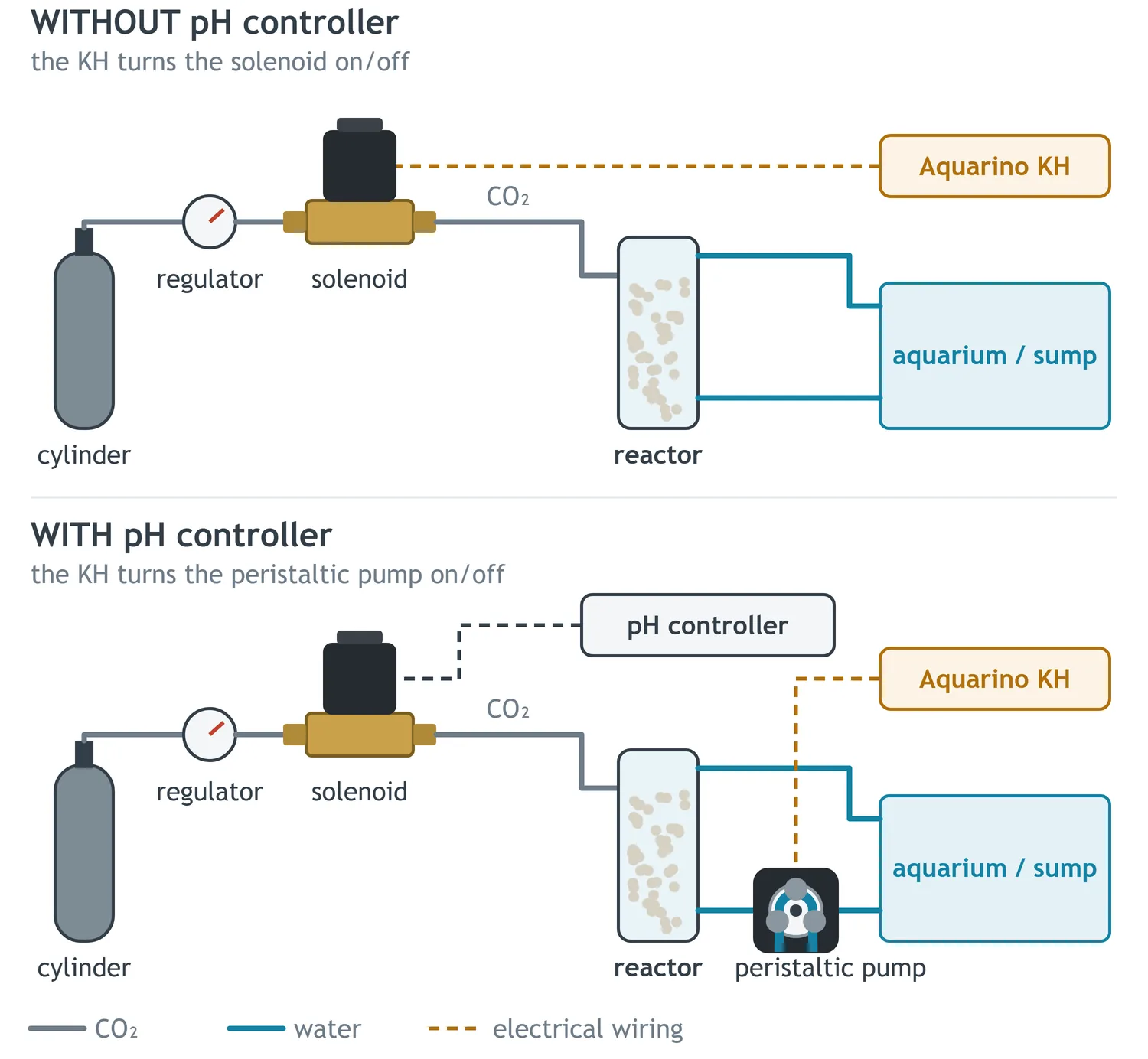
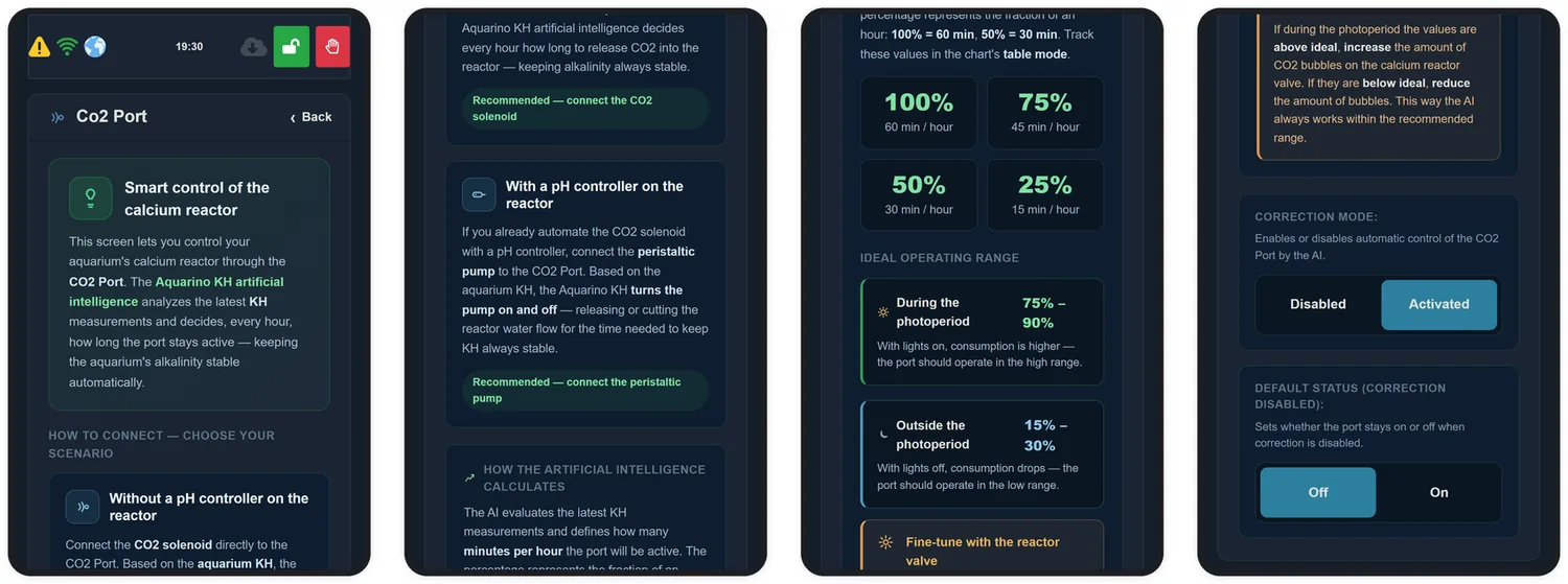
How the CO2 Port works
The CO2 Port is a switch. When the equipment switches the port on, the IN terminal is connected to the OUT terminal; when it switches off, the two are kept apart. The two N terminals are connected to each other inside the equipment and simply pass the second wire through.
The Aquarino KH does not supply power on this port. Power comes from outside, through IN, and leaves through OUT exactly as it came in: if you connect a 220 V outlet to IN, 220 V comes out of OUT; if you connect a 12 V power supply, 12 V comes out. That is why the solenoid or the pump must be rated for the same voltage you feed into the input.
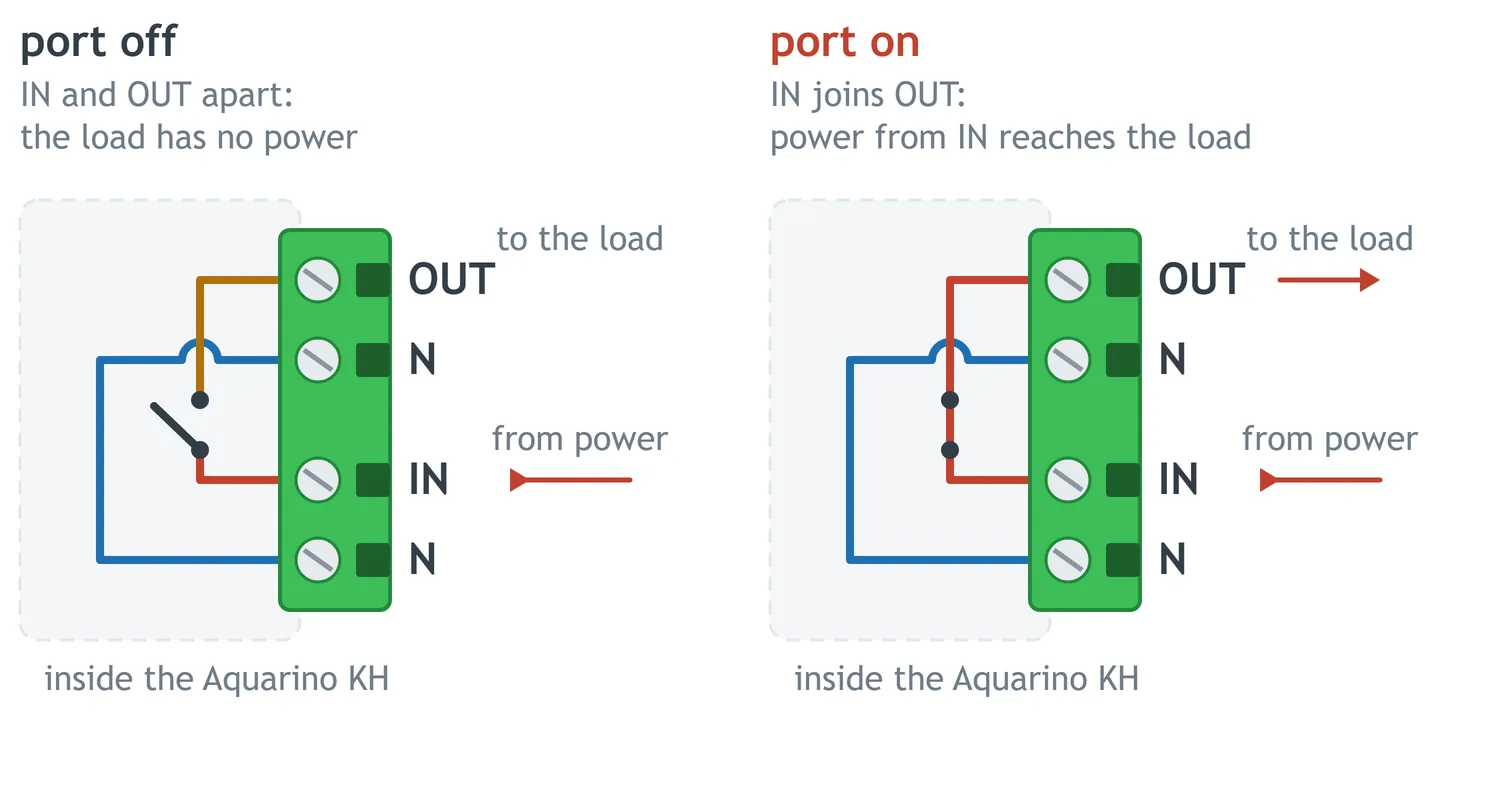
The four terminals
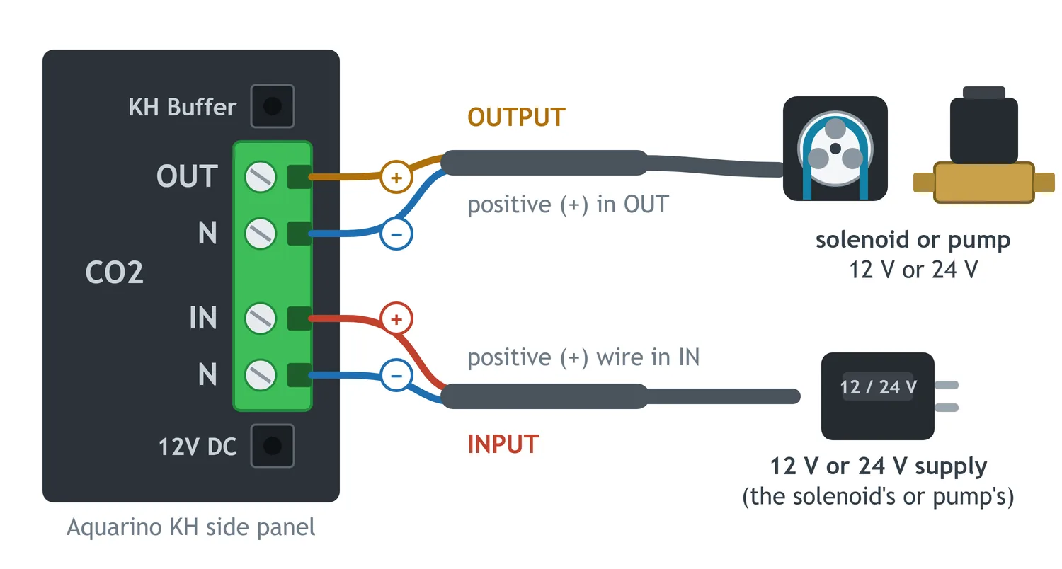
The green connector comes off the panel when you pull it outward, and the wires are held by the connector's own screws. The order, from top (KH Buffer side) to bottom (12V DC side), is:
| Terminal | What to connect |
|---|---|
| OUT | One wire of the cable going to the solenoid or the peristaltic pump |
| N | The other wire of the same cable |
| IN | One wire of the cable bringing in power: wall outlet or power supply |
| N | The other wire of the same cable |
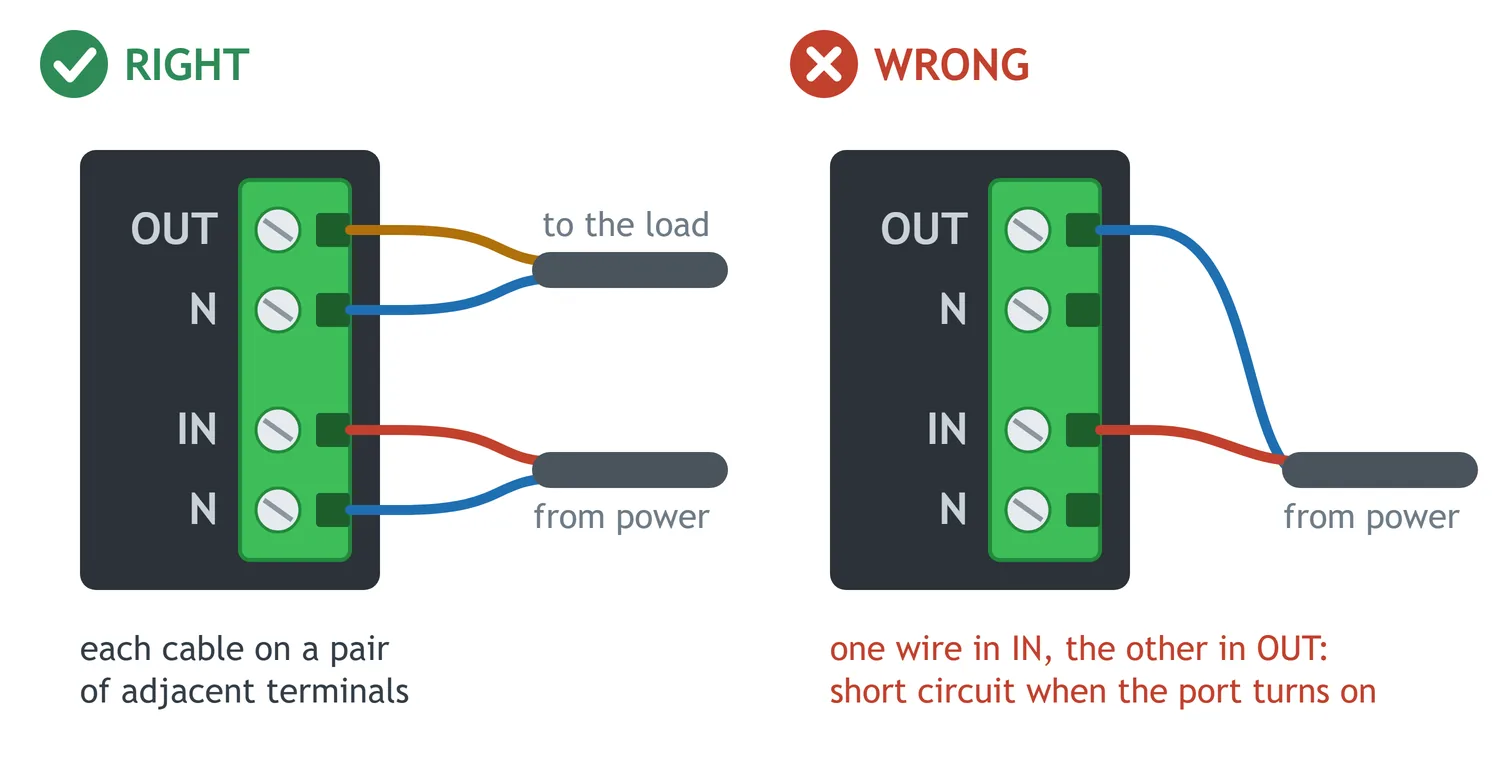
In practice: the top pair is the output, the bottom pair is the input, and each cable takes one pair of neighbouring terminals.
Wiring with a wall outlet (127 V or 220 V)
This is the setup most users build, with two two-wire cables of about 1 metre each: one with a male plug at the end, which goes into the wall outlet, and another with a female socket at the end, where you plug in the solenoid or the pump.
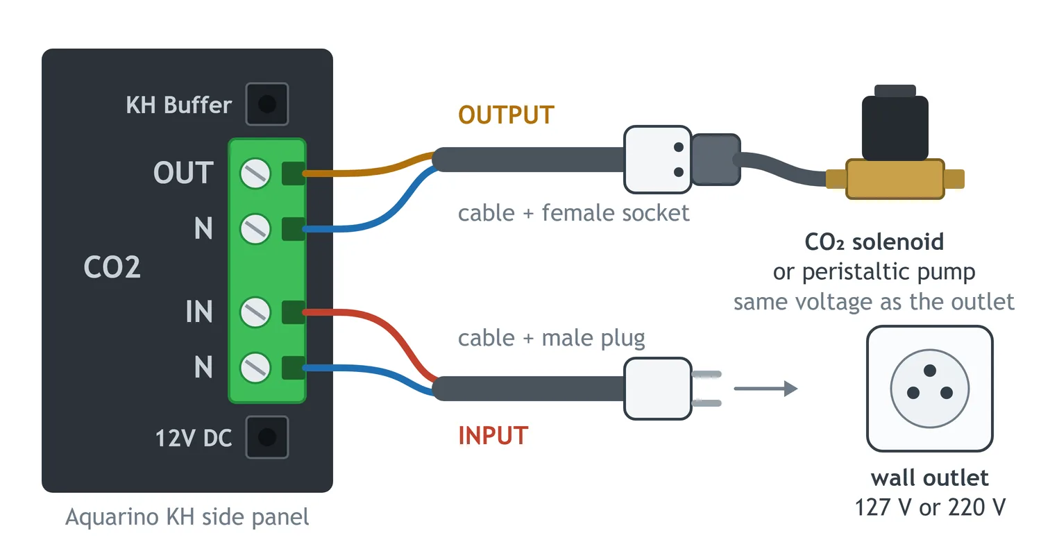
- Keep both cables unplugged from the wall during the whole assembly.
- Remove the green connector from the panel by pulling it outward.
- Strip the end of each wire just enough for the copper to go fully into the terminal, with no bare copper left showing outside.
- Cable with the male plug: one wire in IN, the other in the N just below it. If your installation identifies the live wire, put the live wire in IN; with a two-pin plug, the order of these two wires does not affect operation.
- Cable with the female socket: one wire in OUT, the other in the N just below it.
- Tighten the screws firmly and pull each wire gently to check it is held.
- Fit the green connector back into the panel, plug the solenoid or the pump into the female socket and, last of all, plug the male plug into the wall outlet.
Wiring with a 12 V or 24 V power supply
If your solenoid or pump runs on its own 12 V or 24 V power supply, the supply takes the place of the wall outlet: the supply wires go on the bottom pair and the load wires on the top pair. Here polarity matters: supply positive in IN, negative in N; load positive in OUT, negative in N.
The mistake you must avoid
Limits and precautions
- Maximum port load: 5 amperes. An aquarium CO2 solenoid or peristaltic pump draws far less than that.
- The solenoid or the pump must be rated for the same voltage you feed into IN.
- Connect only the reactor's solenoid or pump to the CO2 Port. It was not designed for heaters, lighting or other equipment.
- Only handle the green connector with both cables unplugged from the wall.
Test after wiring
Before handing the reactor over to automatic control, confirm the wiring works. With Correction mode disabled, the port follows the Default status (section 17.2):
- Change the Default status to On: the solenoid should click, or the pump should start turning.
- Set the Default status back to Off: the solenoid should click again, or the pump should stop.
- If nothing happens, check that the input cable is plugged into the wall and that each wire is in the right terminal.
17.2 Correction mode and default status
| Setting | What it does |
|---|---|
| Correction mode | Enables or disables automatic control of the CO2 Port. It ships Disabled |
| Default status | Sets whether the port stays on or off when automatic control is disabled, or when the equipment has no basis to decide — during filling, emptying, or right after startup |